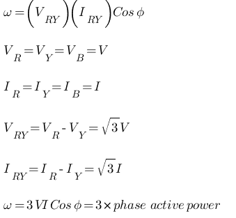
To measure the 3-φ power in a balanced circuit, the method or main apparatus used here are 2 CT’s and one Wattmeter. The details of the apparatus required for this measurement are as follow:
- Wattmeter 600V, 10A, UPF -> 1 no.
- Ammeter (0-10)A MI -> 1 no.
- Voltmeter (0-600)V MI -> 1 no.
- Current Transformer (CT) 5/5A -> 2 no.
In this method the power absorbed in a 3-φ balanced circuit is measured using a single wattmeter in conjunction with 2 CT’s. Usually 2-Wattmeter method is used measure the 3-φ power for both balanced and unbalanced load, but method like this requires only one wattmeter. The CT’s used for this method should be of 1:1 ratio.
The primaries are connected in series with the 2 phases. The secondaries are connected to the current coil of wattmeter such that the difference in the two phase currents will flow through the current coil. The wattmeter pressure coil is connected between the same two phases.
Any wattmeter measures the product of
- Voltage across pressure coil
- Current through the current coil
Cosine of phase angle between voltage and current is φ.
The circuit is assumed to be connected in star, for delta connection also the procedure is valid and the wattmeter reads directly total power absorbed.
Procedure
- Give the connections as per the circuit diagram.
- Apply 415 V, 3-φ, 50Hz supply closing the TPST switch.
- Vary the load in suitable steps.
- At each load note down the wattmeter readings.
- Tabulate the results. Expected example tabulated results are as follows:
S.No VL (Volts) IL (Amps) Wattmeter Reading (Watts) ω Calculated (1.732VLIL Cosφ) 1. 415 2.4 480 x 4 = 1920 1725.12 2. 415 3 600 x 4 = 2400 2156.2


This is truly helpful, thanks.