Our aim here is to calibrate the given Single-Phase Energy Meter using a precession Wattmeter and stopwatch using or employing phantom loading. The main apparatus required for conducting this practical experiment include:
- Single-Phase Induction type Energy Meter – 240V (5-10)A
- Wattmeter 300V/10A UPF
- Phase Shifting Transformer 440V/440, 500VA
- Single-Phase Variac – 240V / (0-270)V
Procedure for calibration and testing of Single-Phase Energy Meter:-
- Give the connections as per the circuit diagram above.
- Apply 220V A.C to the pressure coil circuit by means of phase shifting transformer.
- Apply a load of 2 Amps by switching on the load.
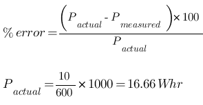
- Note down the reading of two meters in a given period of time, say 2 minutes.
- Find out the percentage error at this load.
- Now rotate the rotor of phase shifting transformer so that the working power factor (p.f) of the meter is varied.
- For this power factor repeat steps 4 and 5.
- Now increase the load current in suitable steps and repeat the steps 4,5,6 and tabulate the results. The expected example results are given in the table below:
S.No Current I(A) Power Factor Wattmeter (w)x2 Time (T) in Hours Measured Power (Whr) % error 1. 5 UPF 1160 0.0105 12.18 23.87 2. 5 0.8 lead 720 0.0180 12.96 19 3. 5 0.8 lag 1120 0.0105 11.76 26.5 4. 4 unity 920 0.0136 12.512 21.8 5. 4 0.8 lead 560 0.0227 12.712 20.55 6. 4 0.8 lag 880 0.0133 11.704 26.85 7. 3 unity 680 0.0177 12.036 24.775 8. 0.8 lead 440 0.0297 13.068 13.068 18.32 9. 3 0.8 lag 680 0.0180 12.24 23.5
Thus we’ve done the testing and calibration of a given Single-Phase energy meter.

